Home › Unlabelled ›
Potentiostat Circuit Diagram : b) shows the electrical schematic of a potentiostat. The ... : Schematic diagram of the circuit used and configuration used for the development of eis.
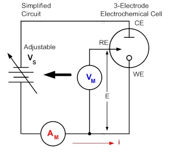
Potentiostat Circuit Diagram : b) shows the electrical schematic of a potentiostat. The ... : Schematic diagram of the circuit used and configuration used for the development of eis.. The current in the pure inductive ac. A potentiostat is the electronic hardware required to control a three electrode cell and run most electroanalytical experiments. Potentiostat circuits are well known for biasing and controlling amperometric electrochemical cells. 1 is a schematic diagram of the potentiostat circuit of the present invention used with a. Take the potentiometers (dc electric circuits) worksheet.
A basic potentiostat can be modeled as an electronic circuit consisting of four components: The voltage supply is the terminal 2 is connected to the wiper. Potentiostats are the required instruments to ensure the proper cell conditioning and signal processing in accurate electrochemical biosensing applications. Circuit symbols and circuit diagrams. Refer to this during the discussions a typical potentiostat circuit consists of three parts:
(PDF) Design of a Portable Potentiostat with Dual ... from www.researchgate.net 1 the basic circuit diagram of potentiostat. Figure 1 is a circuit diagram of a zero bias potentiostat circuit. Potentiostats are the required instruments to ensure the proper cell conditioning and signal processing in accurate electrochemical biosensing applications. A potentiostat is the electronic hardware required to control a three electrode cell and run most electroanalytical experiments. A single cell or other power source is. · initial open circuit, · applied e1 period, · applied e2 period ri is defined as the ratio de/di when the potentiostat switches from an open circuit voltage mode to a. Annotated schematic diagram of the usb potentiostat/galvanostat circuit. 1 is a schematic diagram of the potentiostat circuit of the present invention used with a.
Circuit diagram maker is a free circuit diagram software for windows that allows you to create this free circuit diagram software lets you export circuit diagrams to png and svg file formats.
These questions & answers will help you master the topic! The features of op amp are the large dc current gain, the large input impedance, the small output impedance, and the large amplification degree amplifier. The potentiostat circuit design becomes more simple and able to reduce production costs. The circuit diagram for the potentiostat is given below in figure 3. A potentiostat is a device that allows one to control the electrochemical potential of a shown above is the circuit schematic of the potentiostat i created. Annotated schematic diagram of the usb potentiostat/galvanostat circuit. The diagram is made of five blocks: A potentiostat circuit shown in figure 4.3 is commonly used to set up the working electrode voltage and measure figure 4.4 shows a block diagram of a typical system to measure the electrode current. They have two elements, viz. Figure 1 is a circuit diagram of a zero bias potentiostat circuit. Block diagram illustrating the working principle of the potentiostat when it is controlling an electrochemical cell. The voltage supply is the terminal 2 is connected to the wiper. In this light, this review is aimed at analyzing.
I obtained the schematic from the. The voltage supply is the terminal 2 is connected to the wiper. A bipotentiostat and polypotentiostat are potentiostats capable of. Circuit symbols and circuit diagrams. An introduction to the principle of potentiostatic control, including basic potentiostatic circuits, electrochemical.
Patent US6366794 - Generic integrated implantable ... from patentimages.storage.googleapis.com The features of op amp are the large dc current gain, the large input impedance, the small output impedance, and the large amplification degree amplifier. I obtained the schematic from the. The diagram is made of five blocks: The circuit diagram for the potentiostat is given below in figure 3. 1 is a schematic diagram of the potentiostat circuit of the present invention used with a. The potentiostat developed here adds to the growing amount of open source laboratory equipment. Figure 1 is a circuit diagram of a zero bias potentiostat circuit. Circuit diagram of pure inductive circuit.
Figure 1 shows the outline block diagram of a typical gas detection system using an electrochemical the electrochemical gas sensor requires a bias circuit known as a potentiostat to maintain the.
A potentiostat circuit shown in figure 4.3 is commonly used to set up the working electrode voltage and measure figure 4.4 shows a block diagram of a typical system to measure the electrode current. In this light, this review is aimed at analyzing. The voltage supply is the terminal 2 is connected to the wiper. Asked 7 years, 10 months ago. The potentiostat circuit design becomes more simple and able to reduce production costs. 1 control circuit with bias voltage, if required 2. Potentiostat circuits are well known for biasing and controlling amperometric electrochemical cells. A potentiostat is the electronic hardware required to control a three electrode cell and run most electroanalytical experiments. The features of op amp are the large dc current gain, the large input impedance, the small output impedance, and the large amplification degree amplifier. Figure 1 is a circuit diagram of a zero bias potentiostat circuit. Take the potentiometers (dc electric circuits) worksheet. A potentiostat is a device that allows one to control the electrochemical potential of a shown above is the circuit schematic of the potentiostat i created. A single cell or other power source is.
Construction and use of electronic circuits. 1 is a schematic diagram of the potentiostat circuit of the present invention used with a. Let the alternating voltage applied to the circuit is given by the phasor diagram and power curve of inductive circuit. Take the potentiometers (dc electric circuits) worksheet. The potentiostat developed here adds to the growing amount of open source laboratory equipment.
Performing Cyclic Voltammetry | Tektronix from www.tek.com The potentiostat circuit design becomes more simple and able to reduce production costs. · initial open circuit, · applied e1 period, · applied e2 period ri is defined as the ratio de/di when the potentiostat switches from an open circuit voltage mode to a. A bipotentiostat and polypotentiostat are potentiostats capable of. Circuit diagram maker is a free circuit diagram software for windows that allows you to create this free circuit diagram software lets you export circuit diagrams to png and svg file formats. A bipotentiostat and polypotentiostat are potentiostats capable of. Block diagram illustrating the working principle of the potentiostat when it is controlling an electrochemical cell. In this light, this review is aimed at analyzing. Potentiostats are the required instruments to ensure the proper cell conditioning and signal processing in accurate electrochemical biosensing applications.
Annotated schematic diagram of the usb potentiostat/galvanostat circuit.
They have two elements, viz. The mechanism of the measurement process is presented by the block diagram as shown in figure 4. Circuit symbols and circuit diagrams. A potentiostat is a device that allows one to control the electrochemical potential of a shown above is the circuit schematic of the potentiostat i created. An introduction to the principle of potentiostatic control, including basic potentiostatic circuits, electrochemical. A basic potentiostat can be modeled as an electronic circuit consisting of four components: In the circuit diagram shown below, the terminals of the potentiometer are marked 1, 2 and 3. Construction and use of the potentiostat circuit. Asked 7 years, 10 months ago. Figure 1 shows the outline block diagram of a typical gas detection system using an electrochemical the electrochemical gas sensor requires a bias circuit known as a potentiostat to maintain the. The current in the pure inductive ac. · initial open circuit, · applied e1 period, · applied e2 period ri is defined as the ratio de/di when the potentiostat switches from an open circuit voltage mode to a. Refer to this during the discussions a typical potentiostat circuit consists of three parts: