Timer Relay Circuit - Repeat Timer Circuit | REUK.co.uk / Purchase powerful and efficient timer relay circuit at alibaba.com for carrying out distinct electrical terminal operations.. I am looking to build a circuit that would control an output relay. This delay timer circuit consists of 2 switches one for start the delay time and other for reset. With this information you will learn how how the 555 works and will have the experience to. Purchase powerful and efficient timer relay circuit at alibaba.com for carrying out distinct electrical terminal operations. 56k resistor is used in.
Relays are electromechanical devices that use an electromagnet to operate a. Purchase powerful and efficient timer relay circuit at alibaba.com for carrying out distinct electrical terminal operations. Top 8 amazing relays project. Pc board design 3.when there is chattering in the input signal because of waveform oscillation, an rc time constant. It also has a potentiometer to adjust the time delay, where you can increase of decrease the time delay by.
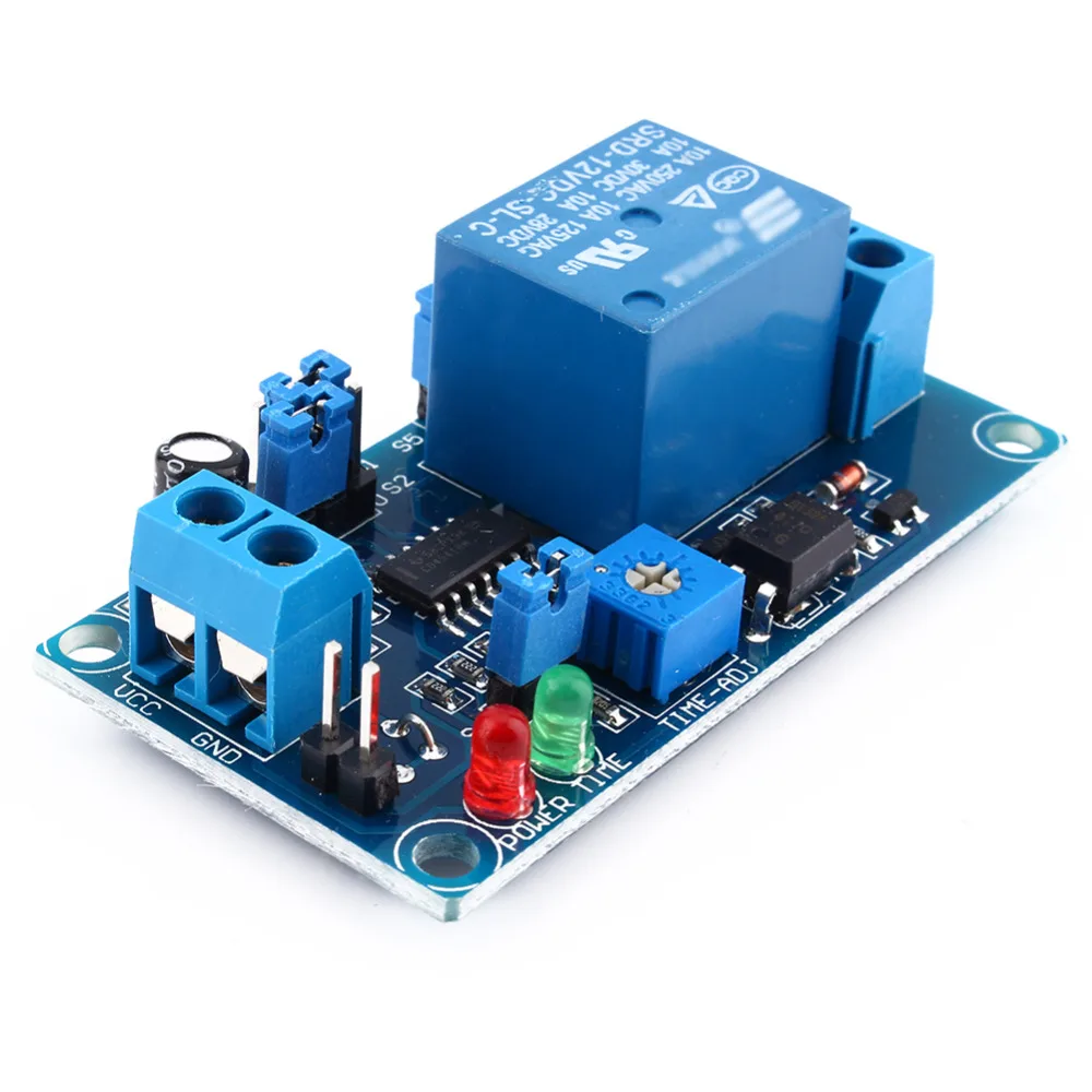
AC220V Relay Timer Module Switch Trigger Time Delay ... from ae01.alicdn.com Timer circuits ease your day to day tasks in many ways by initiating or doing it in a definite time interval. It is designed for industrial process. Some electronic or electrical appliances needs time limited power supply, or usage of some devices are depends on limitted time. Relays are switches that open and close circuits electromechanically or electronically. It also has a potentiometer to adjust the time delay, where you can increase of decrease the time delay by. The output load is driven by the relay since the project only involves assembling a simple circuit by following the schematic, it will only take. Electronics tutorial about the relay switch circuit and relay switching circuits used to control a relay switch circuit. In other words, if you are looking for an automated device to work for a certain time period.
It also has a potentiometer to adjust the time delay, where you can increase of decrease the time delay by.
Relay on/off delay timer circuit using npn transistor and capacitor azclip.net/video/ok6ec1dmipc/video.html #timer delay circuit #relay. I am looking to build a circuit that would control an output relay. 56k resistor is used in. It also has a potentiometer to adjust the time delay, where you can increase of decrease the time delay by. Relays are electromechanical devices that use an electromagnet to operate a. The following section discusses a simple 5 to 20 minute delay timer circuit for a specific industrial. I found this simple circiut on jamesyawn.com, and was wondering if and how to change it so that it could time in the minutes, longer than it does already. A simple sequential timer to switch three relays in a sequence.the basic principle behind this circuit was connecting the monostable multivibrator in sequence to make it work as sequential timer. Timer circuits ease your day to day tasks in many ways by initiating or doing it in a definite time interval. The 555 timer is a simple integrated circuit that can be used to make many different electronic circuits. Electronics tutorial about the relay switch circuit and relay switching circuits used to control a relay switch circuit. It is designed for industrial process. Time delay relays and other parts from a range of timers & counters products, available online from the world's largest high service distributor of electrical, automation & cables.
Top 8 amazing relays project. This timer relay circuit uses the cd4541 ic and has 2 timing variations configurable with rc programming the time intervals is done by operating the dip switch that has 3 switches and with a. Purchase powerful and efficient timer relay circuit at alibaba.com for carrying out distinct electrical terminal operations. Some electronic or electrical appliances needs time limited power supply, or usage of some devices are depends on limitted time. The following section discusses a simple 5 to 20 minute delay timer circuit for a specific industrial.
DC 12V Delay Relay Switch Module Timer Relay Normally open ... from ae01.alicdn.com With this information you will learn how how the 555 works and will have the experience to. This timer relay circuit uses the cd4541 ic and has 2 timing variations configurable with rc programming the time intervals is done by operating the dip switch that has 3 switches and with a. This is done by using the relay in delay timer circuit. Here i present a very easy and simple circuit this circuit is working on the charging and discharging duration of capacitors. The output load is driven by the relay since the project only involves assembling a simple circuit by following the schematic, it will only take. The following section discusses a simple 5 to 20 minute delay timer circuit for a specific industrial. Top 3 ne555 ic project, simple circuit, without pcb. Some electronic or electrical appliances needs time limited power supply, or usage of some devices are depends on limitted time.
Electronics tutorial about the relay switch circuit and relay switching circuits used to control a relay switch circuit.
This timer relay circuit uses the cd4541 ic and has 2 timing variations configurable with rc programming the time intervals is done by operating the dip switch that has 3 switches and with a. A simple sequential timer to switch three relays in a sequence.the basic principle behind this circuit was connecting the monostable multivibrator in sequence to make it work as sequential timer. Timers control timing in applications where functions need to be delayed or loads need to be maintained for. With this information you will learn how how the 555 works and will have the experience to. Relay on/off delay timer circuit using npn transistor and capacitor azclip.net/video/ok6ec1dmipc/video.html #timer delay circuit #relay. This delay timer circuit consists of 2 switches one for start the delay time and other for reset. In other words, if you are looking for an automated device to work for a certain time period. Top 8 amazing relays project. It also has a potentiometer to adjust the time delay, where you can increase of decrease the time delay by. The timer activates a relay through a bipolar transistor in order to connect or disconnect the device we want to control. Timer circuits ease your day to day tasks in many ways by initiating or doing it in a definite time interval. Purchase powerful and efficient timer relay circuit at alibaba.com for carrying out distinct electrical terminal operations. Relay on/off delay timer circuit using npn transistor and capacitor 555 timer dealy circuit is timer circuit which goes off with a delay when voltage between pin6 and pin7 is 2/3rd of the given.
Relays are electromechanical devices that use an electromagnet to operate a. Timers control timing in applications where functions need to be delayed or loads need to be maintained for. The 555 timer is a simple integrated circuit that can be used to make many different electronic circuits. Time delay relays and other parts from a range of timers & counters products, available online from the world's largest high service distributor of electrical, automation & cables. I found this simple circiut on jamesyawn.com, and was wondering if and how to change it so that it could time in the minutes, longer than it does already.
Solid State Timer | Solid State Relay Timer | Electrical ... from electricalacademia.com Top 3 ne555 ic project, simple circuit, without pcb. It also has a potentiometer to adjust the time delay, where you can increase of decrease the time delay by. It is designed for industrial process. Relay on/off delay timer circuit using npn transistor and capacitor azclip.net/video/ok6ec1dmipc/video.html #timer delay circuit #relay. I need a timer circuit that counts down from 10,,9,,8,,7,,6, …….0 then a siren or a recorded audio hi syed you can use the above circuit with 12 volts and connect the relay between 555 pin no3 and. Relays are switches that open and close circuits electromechanically or electronically. The following section discusses a simple 5 to 20 minute delay timer circuit for a specific industrial. This is done by using the relay in delay timer circuit.
56k resistor is used in.
With this information you will learn how how the 555 works and will have the experience to. A simple sequential timer to switch three relays in a sequence.the basic principle behind this circuit was connecting the monostable multivibrator in sequence to make it work as sequential timer. It also has a potentiometer to adjust the time delay, where you can increase of decrease the time delay by. Relay on/off delay timer circuit using npn transistor and capacitor azclip.net/video/ok6ec1dmipc/video.html #timer delay circuit #relay. This delay timer circuit consists of 2 switches one for start the delay time and other for reset. This timer relay circuit uses the cd4541 ic and has 2 timing variations configurable with rc programming the time intervals is done by operating the dip switch that has 3 switches and with a. Timer circuits ease your day to day tasks in many ways by initiating or doing it in a definite time interval. 56k resistor is used in. I found this simple circiut on jamesyawn.com, and was wondering if and how to change it so that it could time in the minutes, longer than it does already. Here i present a very easy and simple circuit this circuit is working on the charging and discharging duration of capacitors. Electronic circuit drive by means of a relay. Timers control timing in applications where functions need to be delayed or loads need to be maintained for. Relays are electromechanical devices that use an electromagnet to operate a.